A signal lamp is needed to be switched on if a pump is strolling and the strain is great, or if the lamp take a look at switch is closed. For the inputs from the pump and the pressure sensors we've an and good judgment scenario on account that each are required if there is to be an output from the lamp. We, however, have an or common sense state of affairs with the test switch in that it is required to give an output of lamp on irrespective of whether or not there may be a sign from the and device. The function block diagram and the ladder diagram are thus of the form shown in figure below. Note that with the ladder diagram we tell the plc when it has reached the end of the program by the use of the end or ret instruction,
 |
| Signal lamp task |
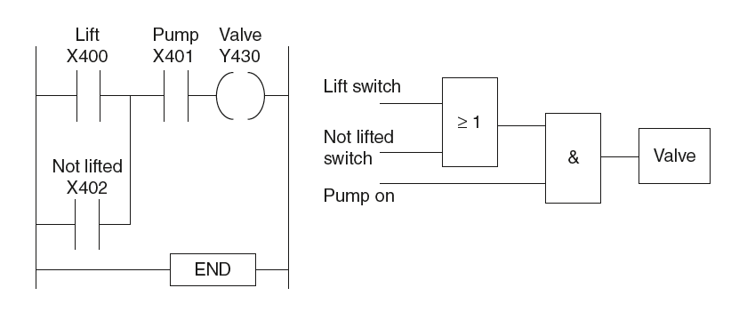
As another instance, keep in mind a valve that is to be operated to raise a load when a pump is jogging and both the raise transfer is operated or a transfer operated indicating that the load has now not already been lifted and is at the bottom of its lilt channel. We've an or scenario for the two switches and an and state of affairs concerning the 2 switches and the pump. Figure under indicates a probable application.
 |
| Valve operation program |
As every other instance, do not forget a gadget wherein there needs to be no output while anybody of four sensors gives an output, otherwise there's to be an output. One way we ought to write a application for this is for each sensor to have contacts which might be usually closed so there is an output. While there may be an input to the sensor the contacts open and the output stops. We've an and good judgment state of affairs. Discern under shows the useful block diagram and the ladder diagram of a machine that might be used.
 |
| Output switched off by any one of four sensors being activated |


Dear visitor. Click on "Follow" button from right side above and sign in with your Gmail account. Write unlimited comments on every post. 100% Free